
Tallguide ®
Ultra Low Loss Waveguide
![]()

Introduction
Tallguide (TALLGUIDE ®) is an ultra low loss waveguide replacement for standard WR type waveguide. Side by side comparisons, in dB per foot, establish factors of 10 improvement in transmission loss. Transition into and out of Tallguide is by electroformed transition units. Tallguide has all necessary components to design any waveguide run from transmitter to antenna. Between the Tallguide transition units are bends, twists, several straight sections and mode suppressor. Tallguide is multi-mode. Even with precision components, a small amount of higher order modes are still excited. Absorbing all higher order modes, the mode suppressor preserves signal linearity. Since Tallguide wavelength is longer than standard waveguide, signal linearity is actually improved. For power users, Tallguide power handling capability is typically 4 to 5 times higher than the power amount safely carried by standard waveguide. Therefore, Tallguide may be used in place of water cooled or air-fin cooled waveguide runs. Where satellite uplinks are limited by maximum EIRP, Tallguide replacement runs typically liberate 4 to 5 dB. Such power savings may be used to scale down antenna size by 40 percent. Along with antenna size cost reductions, come substantial savings in site civil works and installation costs. Tallguide is installed like ordinary rectangular waveguide. No special alignment or tools are needed.
 The promise of oversized waveguides for low loss transmission has been under investigation for many years. A few different circular waveguides have been developed for specialized applications. In the circular TEo11 mode, the most common example is the feed for the horn reflector antenna used at most of the terrestrial microwave or satellite earth stations. Mode trapping is not a primary concern for this application.
In the circular TEo0l mode, the primary application is for extremely high power handling capability used in fusion energy research. In this mode the curvature of the E field makes efficient mode suppression difficult.
Tallguide uses precision rectangular waveguides for operation in the TE0l mode. In this mode the E field lines are straight and parallel to the broad wall of the waveguide. Higher order modes are easily suppressed with the use of low loss, high temperature mode suppressor units.
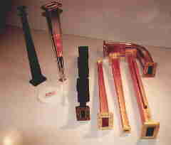
The diagram, illustrates the actual size of a standard waveguide (WR75) and a Tallguide (TG115) for operation in the 10 to 15 GHz range. The transition units, used to convert the standard waveguide to the Tallguide dimensions, feature a sophisticated design to provide mode free operation. The hyperbolic secant H plane bends and non-linear twists also feature mode free operation. This insures zero delay distortion, critical to satellite communications, digital microwave, super radar and ECM applications.
Selection of Tallguide ComponentsAFC can provide the exact Tallguide system to match your requirements. There is a Tallguide band equivalent to each standard WR waveguide band. The thirteen different rectangular waveguide bands described in this sheet cover the common frequency range of 5.8 to 110 GHz. Available options include special designs for unique applications, choice of different flanges, and Tallguide for operation from 5 GHz up to 220 GHz. The Model Selection Table lists the thirteen common different types of Tallguide and the part numbers for each component associated with a particular waveguide. (Links to detailed Tallguide component data sheets for the different Tallguide bands are found within the table.)
Transition units provide the conversion from standard waveguides to the Tallguide dimensions. A transition unit is required at each end of the Tallguide run. Transition units are available with an input cover (-1), or an input grooved (-2) flange for pressure gasket. The straight Tallguide sections are available in any length up to 12 feet. The dash number is used to identify the desired length in inches. For example, a straight Tallguide 10 feet, 6-l/2 inches long would be identified as -126.5. The mode suppressors listed in the table are for the most common application in that particular frequency range. One is required within each Tallguide run. For something out of the ordinary, mode suppressors for special applications may have to be modified to provide optimum performance. Bends in the H plane for Tallguide look like E plane bends in standard waveguides. However, in order to insure mode free operation, the Tallguide bends are limited to H plane bends. To simplify installation, AFC offers 90 degree Tallguide twists. These may be used with Tallguide H plane bends, located after the transition units, to accomplish an E plane bend result.
Low Transmission LossesThe graph illustrates the power savings for Tallguide and the corresponding transmission loss for standard waveguides. Since most radar installations involve a common Tallguide for both a transmit and a receive path, the savings are doubled when considering the overall system. Tallguide power savings, in dB, are a factor of 6 to 10 times better in comparison to standard waveguide. For power users, Tallguide power handling capability is typically 4 to 5 times higher than the power amount safely carried by standard waveguide. With Tallguide, there is no need for water-cooled or air-fin-cooled waveguide. Tallguide is installed like ordinary rectangular waveguide. No special alignment or tools are needed. |
| Frequency Range GHz | Standard Waveguide WRxxx | Tallguide TGxxx | Tallguide Attenuation dB per 100ft. | Component Part Number | |||||||||||||||||
| Transition Units | Straight Sections | Mode Suppressor | H-Plane Bend | 90-deg Twist | |||||||||||||||||
| 5.8 to 8.2 | WR137 | TG215 | 0.28 to 0.24 | 181-1364-x | 181-1368-y | 181-1365 | 181-1367 | 181-1366 | |||||||||||||
| 7.0 to 10.0 | WR112 | TG170 | 0.41 to 0.35 | 181-1167-x | 181-1166-y | 181-1168 | 181-1169 | 181-1170 | |||||||||||||
| 8.2 to 12.4 | WR90 | TG134 | 0.58 to 0.43 | 181-1359-x | 181-1363-y | 181-1360 | 181-1362 | 181-1361 | |||||||||||||
| 10 to 15 | WR75 | TG115 | 0.78 to 0.63 | 181-1078-x | 181-0911-y | 181-1079 | 181-1080 | 181-1081 | |||||||||||||
| 12 to 20 | WR62 | TG87 | 1.25 to 0.93 | 181-0770-x | 181-0769-y | 181-0775 | 181-0782 | 181-0877 | |||||||||||||
| 15 to 22 | WR51 | TG80 | 1.30 to 1.08 | 181-0995-x | 181-0997-y | 181-0996 | 181-0998 | 181-0999 | |||||||||||||
| 17 to 27 | WR42 | TG62 | 1.91 to 1.47 | 181-1082-x | 181-1076-y | 181-1083 | 181-1084 | 181-1085 | |||||||||||||
| 22 to 33 | WR34 | TG50 | 2.71 to 2.05 | 181-1086-x | 181-1087-y | 181-1088 | 181-1090 | 181-1092 | |||||||||||||
| 26 to 40 | WR28 | TG40 | 3.98 to 2.88 | 181-1087-x | 181-0913-y | 181-1089 | 181-1091 | 181-1093 | |||||||||||||
| 33 to 55 | WR22 | TG31 | 6.20 to 4.50 | 181-1374-x | 181-1378-y | 181-1375 | 181-1377 | 181-1376 | |||||||||||||
| 50 to 75 | WR15 | TG23 | 8.50 to 6.80 | 181-1380-x | 181-1384-y | 181-1381 | 181-1383 | 181-1382 | |||||||||||||
| 60 to 90 | WR12 | TG17 | 15.0 to 10.0 | 181-1404-x | 181-1407-y | 181-1408 | 181-1406 | 181-1405 | |||||||||||||
| 75 to 110 | WR10 | TG16 | 17.0 to 13.0 | 181-1385-x | 181-1389-y | 181-1386 | 181-1388 | 181-1387 | |||||||||||||
| x: indicate 1 for input cover flange; 2 for grooved flange. y: section length in inches.
Visit the detailed Tallguide data sheets for the satellite TG115 uplink Ku-band,
Contact the AFC sales department at sales@afcsat.com for other Tallguide bands. |
|||||||||||||||||||||
![]()
AFC manufactures, markets and sells worldwide satellite dish antennas, conical horn antennas, radomes, antenna feeds, microwave and waveguide components, ultra low loss waveguide transmission line Tallguide, and shelters. Our customers serve the broadcast, communications, radar, weather and cable industry, defense, government, and government agencies worldwide.
Additional Tallguide information applied to Satellite Communications is available in "How to Combat Uplink Power Loss" reprinted from Satellite Communications magazine January 1995. Detailed Tallguide component information, for the satellite Ku and DBS uplink frequency bands, may be located in the TG115 and TG87 data sheets. SHF and EHF Tallguide bands maybe retrieved in TG62 and TG31 data sheets respectively. A complete AFC Internet WWW site index may be found in Antennas for Communications (AFC) Home Page Document Summary List.
Top of Page Return to AFC ProfileReturn AFC Home Page

AFC Page Browser
Telephone (352) 687-4121 Fax (352) 687-1203 Email sales@afcsat.com
Tallguide is a Registered Trademark of Antennas for Communications
Copyright © 1996, 1997, 1989, 1999, 2000, 2001 Antennas for Communications