 Competing Antenna Requirements
for Dual-Band Satellites
By Dr. Ronald S. Posner
Antennas for Communications
reprinted from CED Magazine March 1994
Introduction
 It is happening again. The satellites and programmers are on the move.
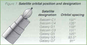
Already C3, Gl, C4 and C l are spaced at 2 degrees-with more to follow. And with the Hughes Communications and Fox Inc. FX announcement, the state-of-the-art dual C/Ku-band satellite, Galaxy G7, is now a "cable bird." Controlling where programming resides, these consortiums, composed of satellite manufacturers and major program providers, continue to exert a powerful, if not direct influence over a cable system's future antenna needs. By most 1994 forecasts, virtually all cable systems must have the capability of receiving a minimum six satellites, plus others for regional sports, pay-per-view and special events. As Figure 1 shows, four of these satellites are at 2-degree spacing. Antenna systems are the cable industry backbone. Television picture quality, in terms of signal clarity (carrier-to-noise ratio), attains perfection at the antenna. No matter what happens to the signal, through distribution and through retransmission, television pictures just get worse. Such stature is due the antenna.
It is happening again. The satellites and programmers are on the move.
Already C3, Gl, C4 and C l are spaced at 2 degrees-with more to follow. And with the Hughes Communications and Fox Inc. FX announcement, the state-of-the-art dual C/Ku-band satellite, Galaxy G7, is now a "cable bird." Controlling where programming resides, these consortiums, composed of satellite manufacturers and major program providers, continue to exert a powerful, if not direct influence over a cable system's future antenna needs. By most 1994 forecasts, virtually all cable systems must have the capability of receiving a minimum six satellites, plus others for regional sports, pay-per-view and special events. As Figure 1 shows, four of these satellites are at 2-degree spacing. Antenna systems are the cable industry backbone. Television picture quality, in terms of signal clarity (carrier-to-noise ratio), attains perfection at the antenna. No matter what happens to the signal, through distribution and through retransmission, television pictures just get worse. Such stature is due the antenna.
 With the satellite arc in constant change, cable operators are now faced with a series of antenna challenges and choices which determine the picture quality of their delivered product. Antenna alternatives not only must take into account minimum picture quality standards, but also headend site factors such as space for new antennas. site viewing arc limitations due to blocking obstacles, environmental factors such as wind and rain fading and signal interference from terrestrial microwave repeater stations.
Whatever antenna solution seems appropriate, problems really start when zoning restrictions and building permits become an essential part of the decision making process. With today's economic climate, antenna options must also be weighed against financial controls and versatility to survive repeated satellite moves. No one wants to invest in an antenna remedy which quickly obsoletes itself whenever a programmer moves to a new satellite.
The following article takes a look at four alternative antenna configurations which dominate the cable industry. The alternatives are the usual prime focus parabolic antenna, upgrading an antenna with a C/Ku-band four port feed, upgrading existing antennas with multisat feeds capable of receiving six or more satellites and conical horn antennas for high interference sites.
Parabolic antenna
 Since the '70s, the simplest satellite antenna type common to the industry is the parabolic antenna. From a technical point of view, the parabolic dish reflector is characterized by two parameters: the dish focal point and diameter. At the focal point a feed system is suspended from supporting spars. The term prime focus feed is used to describe this class of feed system.
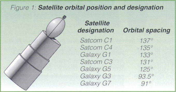
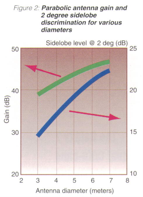
The next dilemma is appropriate antenna size. Antenna diameter determines picture quality through gain and adjacent satellite interference discrimination. Since adjacent 2-degree spaced satellites have like transponders cross polarized to each other, cross pol sidelobe discrimination now becomes the dominate issue. For C-band, Figure 2 displays antenna gain and sidelobe level at 2 degrees for various parabolic antennas sizes common to the industry.
As can be seen from the figure, larger diameter antennas improve picture quality not only from higher signal margins but introduce greater leeway from adjacent interfering 2-degree satellites. Since headend receiving systems work near threshold, an increase of a few decibels in antenna performance gives considerable improvement in the caliber of television (as measured by number of picture defects).

|
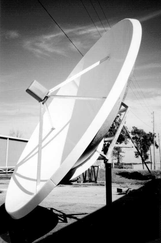
| Figure 4. AFC 3.7 meter diameter pipe mount antenna. |
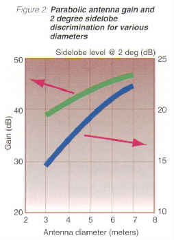
Once an antenna reflector size selection is made, the reflector supporting mount determines how accurate the antenna retains its pointing accuracy. When subjected to gusting wind loads, tremendous forces strain antenna mount and foundation to the limit, as shown in Figure 3. At 125 mph wind speed, Figure 3 describes maximum horizontal shear and overturning moment calculated in 1,000 lbs or 1,000 lbs-ft increments respectively.
Note that wind shear escalates as the reflector diameter is squared, while the overturning moment intensifies approximately as the diameter is cubed. (Mesh antennas suffer the same wind loads as solid dish antennas. Contrary to popular belief, wind does not blow through the screen mesh. When wind hits the mesh, a turbulence boundary layer is formed. This turbulence layer makes the mesh antenna behave as if it where a solid dish.)
When buffeted by random wind loads, mount and feed spar flexure causes random pointing direction errors and therefore signal oscillations. For reasonable performance, pointing errors no larger than 1/4 beam width may be tolerated. C-band random pointing error translates to 0.36 degrees for a 3.7-meter antenna, decreasing to 0.28 degrees and 0.19 degrees as the reflector size increases to 5 meters and 7 meters diameter, respectively.
|
|
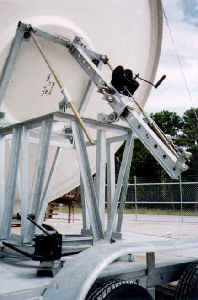
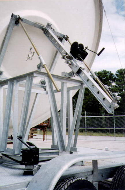
Figure 5. AFC 3.7 meter hand-crank Az/El pedestal. |
A pipe mount is certainly inexpensive, yet the pipe mount has limited lateral wind performance. Other pedestals, characterized by triangular structural truss shapes, are characteristic of high performance antennas (see Figure 5). Of equal importance, antenna spars should be strong and ridged.
Antenna foundation site civil works and installation costs, while hidden, are an increasing part of the antenna budgetary process. Enough foundation concrete is required to sustain the shear and overturning moment forces shown in Figure 3. Antenna assembly takes time, especially when there are a large number of antenna piece parts to worry about. Rushed assembly errors further reduce gain and sidelobe performance. All told, site civil works, assembly and antenna pointing cost money. For each dollar spent on the antenna, reserve one for installation.
Prime focus feed system
Almost every field engineer and technician is familiar with a dual polarized feed system. The reason is that modern C-band satellites have frequency reuse transponders. The dual pol feed is necessary to filter the adjacent partially overlapped vertical and horizontal transponder frequencies signals into the usual two even- and odd-numbered paths. At antenna installation, polarization is adjusted for maximum isolation.
|
|
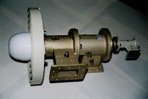
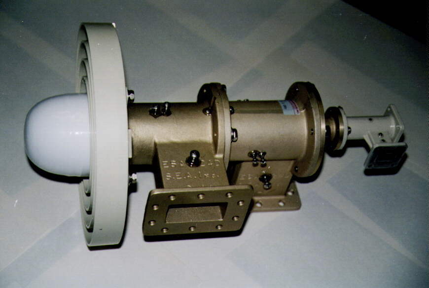
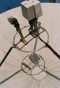
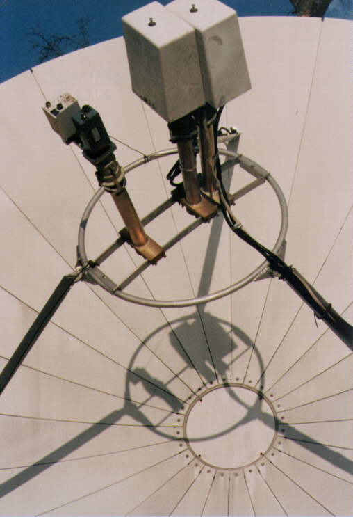
Figure 6. AFC Seavey Engineering four port C/Ku-band feed. |
The Galaxy 7 dual C/Ku-band satellite requirement illustrates the importance of a well-designed feed. Similar to its Galaxy series sisters, the Galaxy 7 satellite is frequency reuse for both C- and Ku-band. Polarization discrimination is therefore required for both bands. Fortunately, the spacecraft C/Ku-band antennas are parallel to each other. As shown in Figure 6, polarization adjustment for one band tunes the other frequency band as well. (For a better antenna system, if you have Ku-band LNBs, point the antenna and adjust polarization for this frequency. Ku-band demands tighter pointing and finer polarization control.)
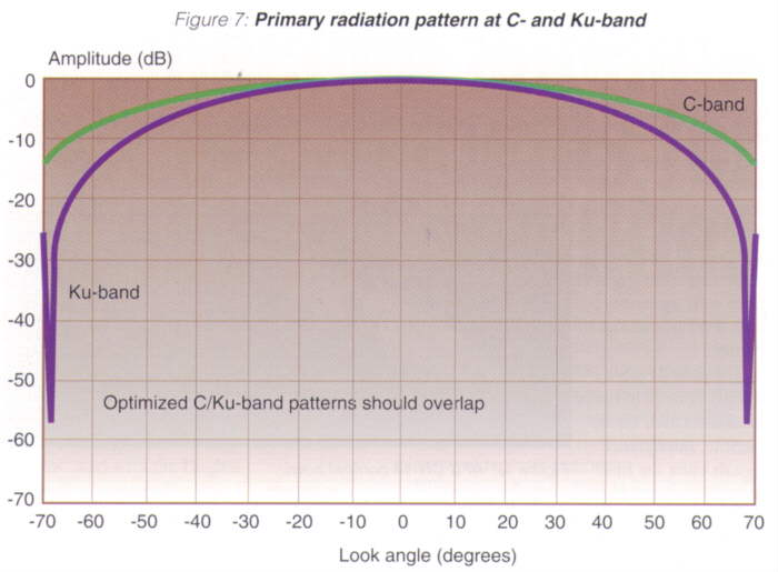
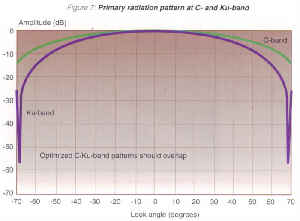 Primary feed radiation patterns must now be f/d optimized simultaneously for both bands. For the experimental, preliminary feed shown in Figure 7, the excessive Ku-band amplitude taper leads to poor Ku-band antenna efficiency compared to C-band. Concurrent C/Ku-band low loss and VSWR and high isolation for the four ports are sophisticated technical problems.
Often, due to competitive pricing pressure, when dual band feeds are introduced from other noncommercial applications, antenna performance is severely hampered.
Gain loss and high noise temperature appear at the expense of one of the frequency bands (several dB loss and 25 degrees extra noise temperature).
Primary feed radiation patterns must now be f/d optimized simultaneously for both bands. For the experimental, preliminary feed shown in Figure 7, the excessive Ku-band amplitude taper leads to poor Ku-band antenna efficiency compared to C-band. Concurrent C/Ku-band low loss and VSWR and high isolation for the four ports are sophisticated technical problems.
Often, due to competitive pricing pressure, when dual band feeds are introduced from other noncommercial applications, antenna performance is severely hampered.
Gain loss and high noise temperature appear at the expense of one of the frequency bands (several dB loss and 25 degrees extra noise temperature).
Multi-sat feeds
The earth station space crunch at headends has come to the point where many headends simply do not have any more room to add even one more dish.
 At low elevation angles found in the northeastern part of the United States, space limitations caused by surrounding trees and buildings severely restrict the satellite viewing arc. Of course, there are alternatives to the space crunch. One can always buy or lease adjacent property or move the headend. Not counting the complexity and politics of local zoning requirements, moving the headend is an expensive proposition.
A preferable solution is to make existing antennas multi-satellite. Many cable systems have an investment in many 4.5- to 7-meter antennas. These antennas are ideal candidates for retrofitting with a Multi-Satellite Feed (MSF) system. With one MSF system, seven satellites over 16 degrees of orbital arc may be received simultaneously.
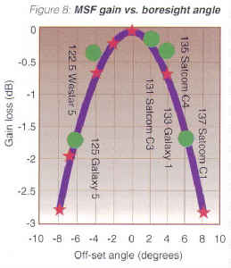
When the feed of a parabolic antenna is displaced at an offset angle from the focal point, the main beam radiation pattern moves in the opposite direction at nearly the same angle. A scanned beam shows a decrease in antenna gain. Sidelobes in the direction of the scan are suppressed and the trailing sidelobes increase. For the 2-degree satellite arc, a 6 degrees scan angle produces only modest gain reductions, as shown in Figure 8.
|
| Figure 9. Sammons Communications' SA 5 meter antenna and AFC's MSF feed system. |
Small cable systems are dominated by 3.7 meter antennas. Whether for new programming or to free up an emergency backup dish, the dual beam multi-sat retrofit is a perfect solution to headend space limitations. Smaller antennas have shorter focal length-which for 2 degrees means feeds must be spaced closer together.
Brute force design attempts to bend feed assemblies away from the same overlapping interference volume have led to power suckouts and polarization distortion. Preserving optimum antenna pattern and distortion-free operation, AFC's solution is based on the theory of overmoded dielectric filled waveguide feeds. Figure 10 pictures a dual beam retrofit.
|
|
Figure 10. AFC 3.7 meter PR-12/4 with dual beam retrofit. |
Satellite antennas & high interference
In many cities across the United States, headends are now positioned in the middle of an electromagnetic thunderstorm. Terrestrial microwave repeater stations, operated by the telephone carriers, often use frequencies identical to the 3.7- to 4.0-GHz satellite band. Such repeater stations, with short distances measured in miles from the headend, radiate sidelobe and scattered energy toward earth stations decades more powerful than satellite signals (with path lengths measured in thousands of miles). Often no amount of rejection filtering can remove this type of interference.Without the possibility of frequency coordinating headend sites, especially for new program services, the cable operator is faced with moving the headend to a more remote area. A remote headend means expending money for new property, overcoming new zoning restrictions and microwave backhaul. Fortunately, one of the oldest antenna technologies-the conical horn enables the cable operator to win the battle against high interference sites.
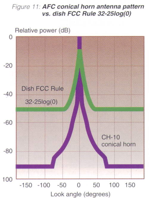
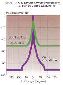 Dish antenna sidelobes are characterized by the FCC rule 32-25*1og(a), where a is the sidelobe look angle until 48 degrees. At 48 degrees, the FCC dish specification retains a constant sidelobe level at -10 dBi. Figure 11 exhibits the dish rule along with antenna pattern from a conical horn antenna. From an interference point of view, the dish antenna pattern and conical horn antenna pattern form a spatial filter with signal envelope levels illustrated in Figure 11.
The peak of the sharply pointed pyramid filter is focused on the satellite. Interference signals enter the filter from directions which are highly suppressed. But with interference signals so much stronger, compared to satellite receive power, the dish 50-dB sidelobe rejection filtering often is just not enough. As can be seen from Figure 11, the conical horn antenna attains another 40 dB of sidelobe rejection margin over the same size dish antenna. Since interference signals may enter the spatial filter at any angle (as a result of bouncing off buildings, trees and everything else), the rejection headroom, in a significant way, may make an otherwise useless headend site useful again.
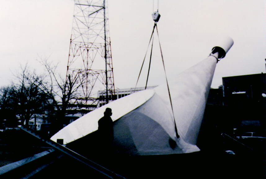
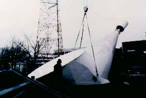
Figure 12 pictures a conical horn antenna. This antenna is a molded, one-piece structure composed of several important manufacturing technologies. Each conical horn uses a three layer sandwich foam core reflector, metalized composite fiberglass horn launcher and sidelobe suppression aperture-all enclosed in a radome for complete weather protection.
|
| Figure 12. AFC CH-14 conical horn. |
Summary
Satellites and programmers are on the move. Syndicates formed by major program providers and satellite manufacturers are forcing a monumental review of headend antenna needs. Now, virtually all cable systems must have the capability of receiving six satellites, plus others for regional sports, pay-per-view and special events. Adding even more complexity (Hughes Communications, Fox Inc. Galaxy 7 FX announcement), cable operators are thrust, for the first time, into dual C/Ku-band satellites.To retain and receive the various programming services, cable operators are faced with a series of antenna challenges and choices which determine the picture quality of their delivered product. This article explores four antenna options facing the cable operator: adding more parabolic antennas, upgrading existing antennas with multi-sat feeds, upgrading antennas with dual C/Ku-band feeds or using the conical horn antenna for high interference sites.
Parabolic antennas continue to dominate the single satellite application. When antenna mount and foundations are designed to accommodate environmental wind loads, pointing accuracy and system gain are maintained. Optimum four-port dual C/Ku-band feeds are presented in terms of the intricate design tasks associated with primary f/d radiation pattern, loss, VSWR and isolation. A multi-sat feed (MSF) system is introduced as a means to reconcile the headend space crunch and reduce cost of receiving additional satellites. Performance data on MSF system antennas are described-giving gain reduction as a function of scan angle. Lastly, the spatial filter representation of an antenna is investigated. The conical horn is shown to give another 40 dB interference rejection headroom over the parabolic antenna.
AFC manufactures, markets and sells worldwide satellite dish antennas, conical horn antennas, radomes, antenna feeds, microwave and waveguide components, ultra low loss waveguide transmission line Tallguide ®, and custom shelters. Our customers serve the broadcast, communications, radar, weather and cable industry, defense, government, and government agencies worldwide.
A complete Internet WWW AFC site index may be found in Antennas for Communications (AFC) Home Page Document Summary List.
Top of Page    Return to AFC Home Page    Return to AFC Profile


    AFC Page Browser
Telephone (352) 687-4121 Fax (352) 687-1203 E-mail sales@afcsat.com
Tallguide is a Registered Trademark of Antennas for Communications Copyright © 1994 CED Magazine