AFC's dielectric radomes have several advantages over other radome type offerings. When the radome panel flange framework is a dilectric material, the radome is called a Dilectric Space Frame (DSF). In contrast, when the panel framework is metal, the radome is called a Metal Space Frame (MSF) radome. DSF radome walls may be constructed as a thin membrane, solid laminate or as multi-layer sandwich with internal foam core. For the thin membrane wall radome, the radome panel flange framework has dimensions capable of supporting the environmental wind loads. Often a two or three layer sandwich wall is used where thermal insulation or where high frequency and low transmission loss requirements prevail. AFC's dielectric radomes have several advantages over other radome type offerings. When the radome panel flange framework is a dilectric material, the radome is called a Dilectric Space Frame (DSF). In contrast, when the panel framework is metal, the radome is called a Metal Space Frame (MSF) radome. DSF radome walls may be constructed as a thin membrane, solid laminate or as multi-layer sandwich with internal foam core. For the thin membrane wall radome, the radome panel flange framework has dimensions capable of supporting the environmental wind loads. Often a two or three layer sandwich wall is used where thermal insulation or where high frequency and low transmission loss requirements prevail.
  Radome transmission loss is composed of two major loss contributions. The first contribution and typically the smallest is the ordinary insertion loss of a signal passing through the radome wall. The second loss contribution comes from signals scattering off the radome panel flange framework. For most frequency bands, framework scattering loss is several times larger than the radome wall insertion loss. When demanding RF transmission loss specifications and structural environmental (wind) loads compete with requirements, DSF radome RF performance may be optimized by a process called impedance matching. Adjacent DSF panel flanges form dielectric beams, which behave as capacitive RF loads. Just as the microwave engineer adds inductive circuit elements to impedance match a capacitive circuit load over a required bandwidth, so does the radome engineer. By laminating just the right amount of inductive circuit elements (wire, metallic strips etc.) into the dielectric flange framework, scattering loss is "tuned out" significantly improving transmission loss. In contrast, the metal space frame (MSF) radome framework blocks the RF energy and you must take what you get without any improvement. For dielectric radomes, on the other hand, it is the wealth of impedance matching compensation alternatives, from no tuning a pure dielectric framework, to a controlled impedance match using wire elements, to even creating an inductive "metal" framework, that the DSF radome out shines any substitute. AFC has performed considerable broad band impedance matching work over the 0.1 to 20 Ghz band. Here various layers of metalized fiberglass are alternately dispersed into the flange fabrication process. Radome transmission loss is composed of two major loss contributions. The first contribution and typically the smallest is the ordinary insertion loss of a signal passing through the radome wall. The second loss contribution comes from signals scattering off the radome panel flange framework. For most frequency bands, framework scattering loss is several times larger than the radome wall insertion loss. When demanding RF transmission loss specifications and structural environmental (wind) loads compete with requirements, DSF radome RF performance may be optimized by a process called impedance matching. Adjacent DSF panel flanges form dielectric beams, which behave as capacitive RF loads. Just as the microwave engineer adds inductive circuit elements to impedance match a capacitive circuit load over a required bandwidth, so does the radome engineer. By laminating just the right amount of inductive circuit elements (wire, metallic strips etc.) into the dielectric flange framework, scattering loss is "tuned out" significantly improving transmission loss. In contrast, the metal space frame (MSF) radome framework blocks the RF energy and you must take what you get without any improvement. For dielectric radomes, on the other hand, it is the wealth of impedance matching compensation alternatives, from no tuning a pure dielectric framework, to a controlled impedance match using wire elements, to even creating an inductive "metal" framework, that the DSF radome out shines any substitute. AFC has performed considerable broad band impedance matching work over the 0.1 to 20 Ghz band. Here various layers of metalized fiberglass are alternately dispersed into the flange fabrication process.
Top of Page.
AFC's DSF panels are a molded one piece process. Thin DSF membrane panels are pre-stressed to form a rigid panel. The prestress process eliminates wavy, flapping panel membranes and eliminates the need for pressurization to reduce oil-canning, sound/vibration noise, microphonics and fatigue failure characteristic of metal space frame (MSF) radomes. Without pressurization, metal space frame radomes are unable to meet wind load speed requirements. With a need for pressurization, a metal space frame radome relies on prime power to run the blower equipment to survive maximum wind loads.
 |
 |
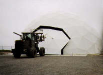
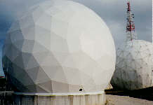
| Dielectric Space Frame (DSF) Radome with Metal Space Frame (MSF) Radome is Background. |
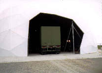
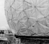
Metal Space Frame (MSF) Radome with Wrinkled, Wavy, Flappy Panels. |
DSF radome panels have never experienced a membrane failure. In contrast to metal space frame radomes, no sound deadening pressurization blowers are needed except as required for air ventilation, circulation purposes. For unattended radome sites, pressurization blowers add another failure mechanism---thereby reducing up-time operational performance and making the radome survival dependent on prime power outages.
 Dielectric radome panels contain no metal beam framework, which corrode in harsh or salt environments. Minimal maintenance is required for dielectric radome panels. In contrast, the metal space frame (MSF) structural framework members experience corrosion, which washes onto the radome surface, adjacent panels members onto adjoining framework beam structure. Not only is corrosion a maintenance problem, but from an RF point of view, corrosion creates numerous diode mixers, which create intermod interfering signal products in the presence of high power, multi-frequency/carriers, characteristic of modern satellite and radar communications systems. In contrast, AFC's dielectric radomes are intermod free
Top of Page.
AFC introduced the use of corner nodal bolts to transfer strut loads to the rest of the radome panels. This creative solution eliminates the need for corner hub load distribution caps common to metal space frame radomes. Nodal bolt technology significantly reduces blockage transmission loss. In contrast, corner hub caps increase antenna blockage and increase radome transmission loss and noise temperature.
When service or antenna update schedules demand radome access for large antenna part removal or entry, DSF panel members are easily removed, reinserted and resealed.
With the DSF panel flanges internal to the radome, dielectric space frame hardware are not exposed to the environment.
AFC has a optional proprietary hydrophobic coating which meets the demands of real systems. This coating forms a chemical bond to the radome surface, is inert to common solvents, is abrasion resistant and may be reapplied in the field, should the radome surface be damaged. AFC's hydrophobic coating retains its vitality and remains bonded to the surface years longer than any commercial "Vellox type" surface preparation. The DSF radome surface is Tedlar for flat faceted radome panels and gelcoat for spherical curved panels.
Top of Page.
 |
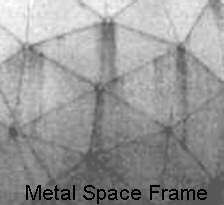
| Metal Space Frame (MSF) Radome |
AFC's thin skin DSF panel membrane is a composite wall with the outer surface layer composed of Tedlar, a material which lasts 20 years. AFC's unique proprietary prestress process simultaneously solves the Tedlar pealing problem, characteristic of bonded composites with dissimilar thermal expansion coefficients.
In order to simplify field installation, DSF radome panel sides are letter coded at the factory, "A" through "E". Since the radome has several different panel types, the letter coding enables installation personnel to assemble like panel code letter edges without relying on misplaced assembly instructions.
For most normal site installations, little to no coordination is required between the radome/installation team and the foundation site preparation group. The reason is that DSF radomes do not require a base ring (compression ring) or precast foundation anchor bolts. (No base ring disagreements need take place over whether the base ring is part of the radome or site civil works price estimates.) Now common practice, AFC has pioneered and field tested for the U.S Army CECOM, a radome base panel assembly technique with the radome foundation which eliminates the need for precision foundation bolt placement. Wedge anchor bolts are bored into the foundation at installation by the installation field crew. No foundation survey, template preparation and accurate anchor bolt insertion into the wet foundation or compression base ring interface need be scheduled or timing anticipated. Thus foundation construction and radome installation become independent activities----removing the usual need for precise coordination. For example at a foreign classified site, an AFC supervisor, along with an unskilled military crew of that country, erected AFC's 68 foot diameter DSF radome in the manner illustrated above. Indeed, removing the need for accurate and meticulous foundation and site coordination assures a timely and successful installation, even under the most trying of circumstances.
Top of Page.

AFC manufactures, markets and sells worldwide satellite dish antennas, conical horn antennas, radomes, antenna feeds, microwave and waveguide components, ultra low loss waveguide transmission line Tallguide ®, and shelters. Our customers serve the broadcast, communications, radar, weather and cable industry, defense, government, and government agencies worldwide.
A complete Internet WWW AFC document index may be found in Antennas for Communications (AFC) Home Page Document Summary List. Additional radome information is contained in the Dielectric Space Frame Data Sheet and AFC's Radome Capability Brochure.
Return to AFC Profile  Return to Radome Network Home Page. Return to Radome Network Home Page.
Antennas for Communications
2499 SW 60th Ave, Ocala, FL 34474
Telephone (352)687-4121 Fax(352)687-1203 E-mail sales@afcsat.com
Tallguide is a Registered Trademark of Antennas for Communications
Copyright © 1996 - 2000 Antennas for Communications
|